Autostereoscopy: Technical Explainer
An objective technical explainer covering autostereoscopy as a glasses-free 3D display method, how it differs from stereoscopic and VR workflows, common optical approaches, and where it fits in professional review workflows.
What autostereoscopy is
Autostereoscopy is the family of display techniques that produce a stereoscopic depth impression without requiring the viewer to wear glasses, headsets, or other head-mounted optics. The word itself combines auto (self) with stereoscopy (solid vision), indicating that the display handles the left-eye/right-eye separation on its own rather than relying on eyewear to filter the views.
In practical terms, an autostereoscopic display is a flat-panel display paired with an optical layer or processing pipeline that delivers different images to each eye. The viewer perceives binocular depth the same way they would with a stereoscopic monitor, but with no glasses, no shutter sync, no polarized filters, and no head-mounted display in the loop.
Because the technique is glasses-free, autostereoscopy is often used as an umbrella term in marketing copy alongside phrases such as “naked-eye 3D,” “glasses-free 3D,” and “3D without glasses.” Underneath that umbrella, the optical implementations vary significantly, and the choice of implementation shapes the viewing experience.
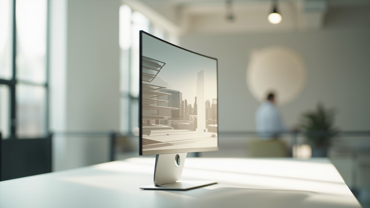
Autostereoscopic displays deliver stereoscopic depth through an optical layer rather than through glasses or headsets.
How autostereoscopy differs from stereoscopy, holography, and VR
Autostereoscopy sits inside a wider 3D display family, and it is easiest to define by contrast.
- Stereoscopic 3D typically requires glasses. Active shutter glasses, polarized glasses, or anaglyph filters are used to deliver separate left-eye and right-eye images. The display itself is comparatively simple, but the workflow depends on the eyewear.
- Autostereoscopic 3D removes the glasses and instead encodes the left/right separation into the optical layer in front of the panel or into the panel itself.
- Holographic and light-field displays aim to reproduce a fuller optical wavefront so that perspective shifts as the viewer moves. True holographic displays remain niche in commercial review environments; light-field approaches overlap with some autostereoscopic multi-view designs, but they are not synonymous with autostereoscopy.
- VR headsets generate stereoscopic depth by placing a display and lens system directly in front of each eye. They are head-mounted rather than monitor-style, and they isolate the viewer from the surrounding room.
The practical consequence is that autostereoscopy preserves a monitor-style workflow. Viewers sit or stand in front of a screen the way they would with any conventional monitor, and the display produces the depth effect inside its normal viewing envelope.
Optical approaches behind autostereoscopic displays
Most commercial autostereoscopic displays are built from one of two broad optical sub-methods, often combined with eye tracking on higher-end models.
- Parallax barrier. A precision barrier with fine slits sits in front of the panel. The barrier blocks parts of the image so that each eye sees a different set of pixels. Parallax barrier designs are typically thin, cost-effective, and well-suited to compact panels. The tradeoffs include reduced brightness and a narrower comfortable viewing zone.
- Lenticular lens array. An array of cylindrical microlenses sits on top of the panel. Each lens refracts the underlying pixels so that different views are projected toward different horizontal angles. Lenticular designs tend to allow brighter images and can support multi-view setups, at the cost of more complex lens manufacturing.
Higher-end implementations add eye tracking (often structured-light based) so the display updates which pixels map to which view as the viewer moves. Tracking widens the comfortable viewing zone and reduces the “sweet spot” problem that fixed-view autostereoscopic displays are known for. Related techniques, such as time-multiplexed or dual-panel designs, exist but are less common in current professional review displays.
Our companion explainer on parallax barrier display technology covers the slit-based approach in more detail, and the broader explainer on autostereoscopic display submethods walks through how these optical choices relate to each other inside the 3D display family.

Parallax barrier and lenticular lens array are the two most common optical approaches used to separate left- and right-eye views.
How a viewer perceives depth
The perception chain is the same one that stereoscopic displays rely on: each eye receives a slightly different 2D image, and the brain fuses them into a depth impression using binocular disparity. What autostereoscopy changes is how those two 2D images are physically delivered.
Three factors shape how convincing the depth looks:
- View separation quality. How cleanly the optical layer routes the left-eye pixels to the left eye and the right-eye pixels to the right eye. Crosstalk between the views reduces depth clarity and can cause ghosting.
- Viewing zone geometry. Where the viewer can sit or stand without leaving the sweet spot. Fixed-view designs have narrow horizontal zones; tracked designs follow the viewer and broaden the zone.
- Source content geometry. Whether the source content actually provides a stereo pair with realistic disparity. A flat 2D image sent through an autostereoscopic pipeline will still look flat; only stereo or 3D-ready content can carry depth.
Tracking and viewer experience tradeoffs
Eye-tracked autostereoscopic displays are the most common premium configuration in professional review environments. Tracking is useful because it solves the most common complaint about glasses-free 3D: that the effect collapses when the viewer moves their head.
There are tradeoffs worth being explicit about:
- Single viewer vs. multi-viewer. Most tracked autostereoscopic displays are tuned for a single primary viewer. Some lenticular designs support two or more simultaneous viewing zones, but each additional zone reduces per-zone resolution.
- Tracking latency. If the eye tracker or the display-side processing introduces visible lag, depth can break during fast head motion. The lag tolerance depends on the specific model and is not always disclosed in detail.
- Glasses and lighting. Unlike active-shutter stereoscopic systems, autostereoscopic displays do not require sync with glasses. However, ambient light, reflections on the optical layer, and the viewer’s prescription glasses can still affect the perceived image quality.
- Resolution per view. Because each eye receives only a subset of the panel’s pixels, effective 2D-equivalent resolution per eye is often lower than the panel’s native pixel count. This matters when comparing published panel specifications against perceived sharpness.
Content compatibility and workflow fit
Autostereoscopic displays are display hardware. They do not generate depth by themselves. The depth effect only appears when the source content is already stereo or 3D-ready, or when a software pipeline converts suitable source material into a stereo pair.
Common compatible content paths include:
- Side-by-side (SBS) stereo video and stills. A standard interchange format for stereo content. SBS pairs map directly onto the left/right views of an autostereoscopic pipeline.
- CAD and 3D model viewers. Tools that can output two perspective views from a 3D scene with controlled camera separation.
- Medical and industrial 3D exports. DICOM volumes, CT scans, and other volumetric data rendered through a stereo-capable viewer.
- Real-time 3D engines. Unity, Unreal, WebGL, and custom 3D applications that can render left/right passes or a multi-view output.
Workflows that do not work well without preparation include:
- Ordinary 2D video and flat images, which carry no disparity to display.
- Single-view 2D application windows that cannot be routed into a stereo output.
- 3D applications that only render a single perspective view at a time.
For teams evaluating whether their existing pipeline can feed an autostereoscopic display, the typical first step is to check whether any part of the workflow can already produce SBS output or multi-view rendering. If not, content preparation becomes a real cost.
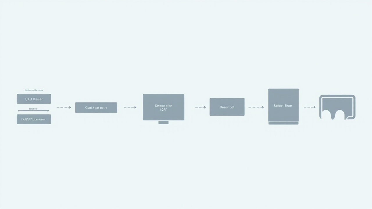
A typical autostereoscopic workflow pairs a stereo-capable source pipeline with eye tracking and display-side processing.
Limitations and uncertainty
A few honest limits of current autostereoscopic technology are worth flagging:
- Narrow viewing zones on fixed-view designs. Without eye tracking, moving off-axis causes depth to break or images to invert between left and right views.
- Reduced brightness and contrast. The optical layer absorbs or refracts some light, so images typically look dimmer than a comparable 2D panel at the same backlight setting.
- Moiré and banding artifacts. Fine textures, grids, and high-contrast text can interact with the microlens or barrier pattern and produce visible artifacts that do not exist on a standard 2D panel.
- Single-viewer ergonomics on most tracked models. Tracked displays follow one viewer; collaborative viewing usually requires stepping out of the sweet spot or relying on multi-view designs with reduced per-view resolution.
- Spec opacity. Manufacturers do not always publish per-view resolution, crosstalk figures, or tracking latency. Headline panel specifications can be misleading when the actual per-eye image quality is what matters for review work.
Next steps for evaluating autostereoscopic displays
For teams moving from “this sounds interesting” to a real evaluation, the practical path looks like this:
- Confirm content readiness. Identify whether the source pipeline can produce SBS stereo, multi-view output, or stereo-capable real-time rendering. Without this, no autostereoscopic display will deliver meaningful depth.
- Decide on tracked vs. fixed-view. Tracked displays are a better fit for single-viewer professional review. Fixed-view designs can work for kiosks, signage, and shared demo setups where the viewer position is roughly controlled.
- Test with realistic source material. Vendor demos typically use optimized content. Bring representative real-world material — CAD assemblies, DICOM volumes, CT stacks — to see how the display handles everyday inputs.
- Plan for the optical layer’s effect on 2D use. If the display is shared between 2D and 3D work, evaluate how brightness, text sharpness, and contrast change when the optical layer is engaged. Higher-end Pro-series designs usually switch modes more gracefully than entry designs.
- Verify ergonomics for the actual user. Viewer height, eye position relative to the panel, and ambient lighting all affect the experience more than they do on a standard 2D monitor.
For a broader buyer-side framing of these tradeoffs, the Spatial 3D Display Buying Guide walks through how autostereoscopic displays sit alongside other glasses-free 3D options. The companion explainers on naked-eye 3D, 3D without glasses, and 3D display screen hardware cover adjacent parts of the same technology stack.
If a specific workflow — medical review, industrial inspection, CAD collaboration, microscope display, or showroom demo — appears to align with the strengths of autostereoscopy, the next step is usually a hands-on evaluation with real source content rather than a specification comparison alone.
Ready to explore 3D displays?
Browse our detailed comparisons and buying guides to find the right spatial display for your workflow.
View Best 3D MonitorsDisclosure: This article is part of 3DMonitor.net's educational content. Product recommendations are based on research and may contain affiliate links. See our full disclosure.