3D Display Screen Hardware Integration: Workstation Builder Guide
Workstation-builder guide to integrating a 3D display screen: signal path planning, GPU output configuration, EDID/HDCP handshakes, viewer placement, mounting, cabling, and thermals for glasses-free 3D review setups.
3D Display Screen Hardware Integration: Workstation Builder Guide
A 3D display screen — specifically a glasses-free autostereoscopic spatial display — only delivers on its potential if the workstation around it is planned as a system. Many integration issues reported as “the display does not work” are actually problems in the signal path, GPU output configuration, EDID/HDCP handshakes, viewer placement, cabling, or thermals. This guide walks through the integration decisions a workstation builder should make before, during, and after physical installation.
If you are still choosing between models, see the Spatial 3D Display Buying Guide or use the Display Selector first. This page assumes a model is already selected and focuses on how to integrate it cleanly.
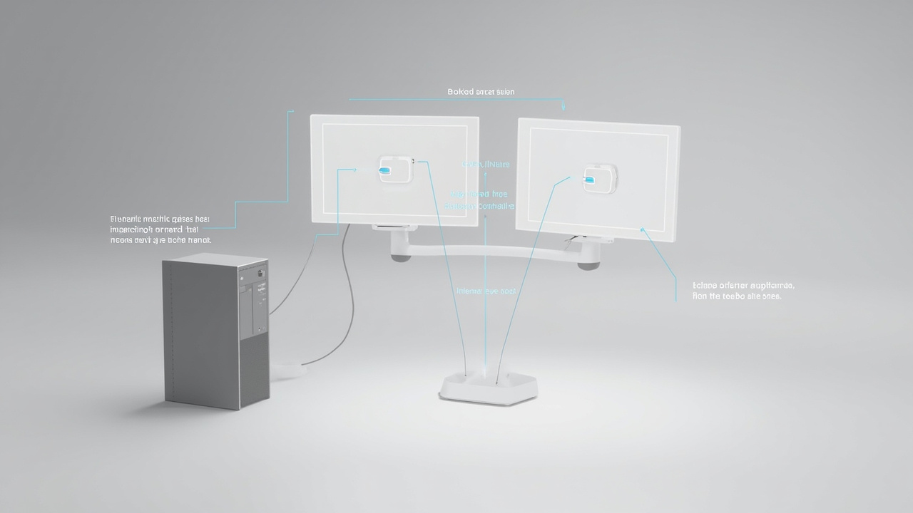
Glasses-free 3D display screen integration: the signal path runs from the host workstation through the GPU, cable, display controller, and optical layer to the viewer’s eyes.
What this guide covers
This is an integration-planning guide for system builders, AV integrators, lab managers, and review-room designers. It does not cover model selection, pricing, or benchmarks. It does cover:
- Signal path planning from the host workstation to the 3D display screen
- GPU output modes and stereo pipeline configuration
- EDID/HDCP handshake behavior and how to debug it
- Viewer placement, eye-tracking sweet spot, and mounting geometry
- Cabling choices, length limits, and signal integrity
- Thermal and acoustic placement around the workstation
For the underlying terminology behind glasses-free 3D, see the Naked-Eye 3D technical explainer and the Autostereoscopic Display submethods explainer. For workflow-versus-headset tradeoffs, see the 3D Without Glasses collaborative review workflow guide.
Signal path planning for a glasses-free 3D workstation
An autostereoscopic 3D display screen requires the host workstation to deliver a tightly timed stereo or multi-view signal. Treat the signal path as a chain with explicit stages:
- Application pipeline. Your 3D, CAD, medical visualization, or microscope source must produce a stereo-compatible frame stream — typically side-by-side (SBS), top-bottom, or a multi-view buffer that the display’s controller can map to its optical layer.
- GPU output stage. The GPU must be configured to emit the display’s native timing, refresh rate, and resolution over the chosen connector. Stereo mode selection happens here.
- Cable run. DisplayPort or HDMI cabling carries the signal from the host to the display’s input panel.
- Display controller and optical layer. The display’s FPGA re-times frames, applies the eye-tracking and view-mapping logic, and drives the lenticular or microlens optical layer.
- Viewer-side sweet spot. The perceived 3D effect only forms at the location the eye-tracking system is currently tracking.
Each link in this chain can silently degrade the experience. A common failure mode is that the GPU outputs a standard 2D timing that the display accepts but does not interpret as stereo — the screen then shows a usable 2D image without throwing any error.
Before purchasing cabling or finalizing the desk layout, verify that your source application can produce a stereo output that the display will accept. The Content-to-3D Path Checker is the recommended validation step.
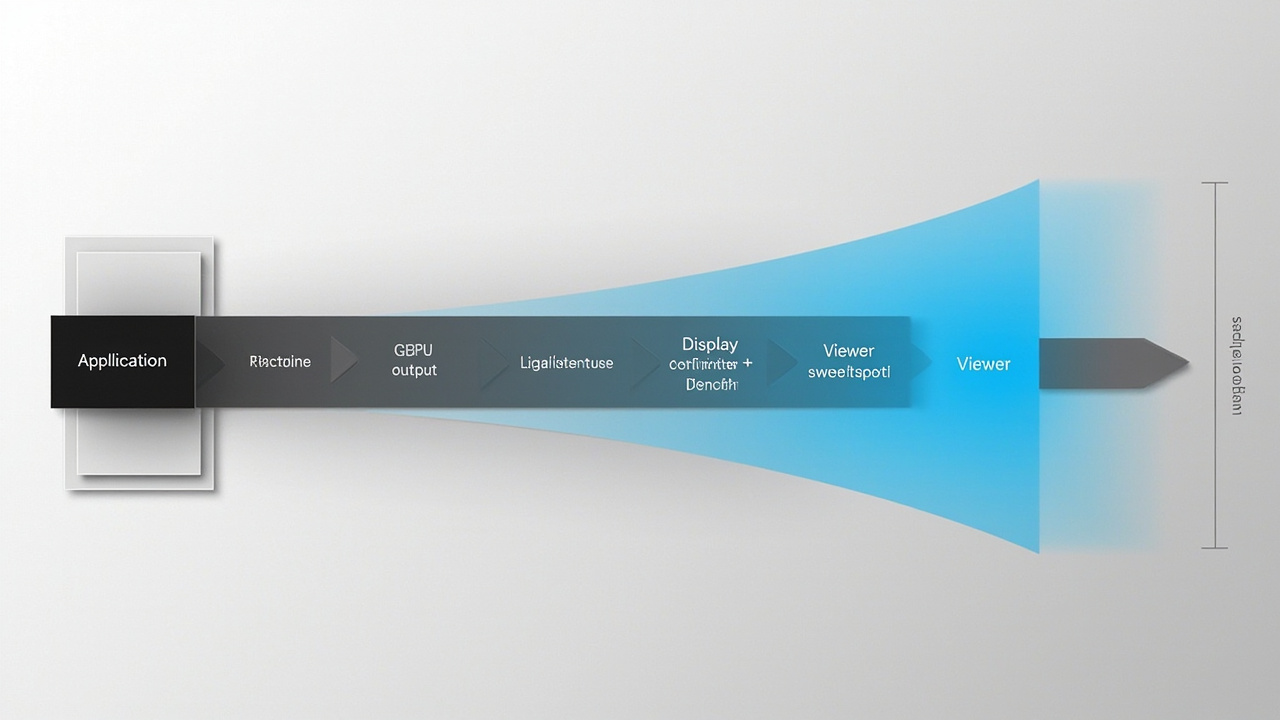
Five-stage signal chain for a 3D display screen: each link can degrade the perceived 3D effect if misconfigured.
GPU output and stereo mode configuration
Three configuration choices dominate GPU-side integration:
- Connector and protocol. Many current autostereoscopic displays prefer DisplayPort for full timing support, with HDMI as a secondary path. Check the specific model’s supported input list against your GPU’s outputs. Adapters can be acceptable for short runs but introduce handshake variability.
- Resolution and refresh. Set a custom timing mode only if the display’s documentation explicitly supports it. Running the panel at a non-native refresh rate can defeat the eye-tracking view-mapping logic.
- Stereo output mode. Configure the application (or the GPU driver layer) to emit the expected stereo format — SBS, top-bottom, or frame-sequential depending on the display. Mismatched mode selection is a frequent cause of “flat” perceived images on otherwise working hardware.
For CAD and 3D model viewers, the stereo mode is usually set inside the application. For custom WebGL, Unity, or Unreal pipelines, mode is set in the rendering layer before the GPU’s display output stage. For DICOM or medical viewers, check whether the viewer emits a stereo-compatible buffer at all before assuming the GPU side is the issue.
EDID, HDCP, and handshake considerations
The Extended Display Identification Data (EDID) block tells the GPU what timings the display accepts. The High-bandwidth Digital Content Protection (HDCP) handshake verifies the link’s authenticity. On a 3D display screen, both deserve attention:
- EDID mismatches. If the host GPU reads a stale EDID, it may offer only 2D timings to the display, or limit color depth to a range the display’s controller does not expect. Re-plugging the cable and rebooting the host is sometimes enough. Persistent mismatches may require a powered repeater or a known-good cable run.
- HDCP failures. Some protected content paths will downgrade or blank stereo content if HDCP negotiation fails. For review workflows on local files, this is rarely a blocker, but it matters for any playback source that enforces content protection.
- Multi-display chains. If the workstation also drives a secondary 2D monitor through a daisy-chain or MST hub, the display chain’s EDID becomes more complex. Isolate the 3D display on its own GPU output where possible.
Debug pattern when “nothing happens”: read the host’s display settings dialog. If the offered resolution/refresh list matches the display’s spec sheet, the EDID read succeeded. If the list is limited to safe-mode timings, treat that as an EDID problem and isolate the cable run before suspecting the panel.
Viewer placement, eye-tracking sweet spot, and mounting
Unlike a passive 3D monitor, an eye-tracked autostereoscopic 3D display screen has a defined viewer sweet spot. The display actively tracks the primary viewer’s eyes and shifts its view mapping in real time. This has three practical consequences for workstation builders:
- Single-viewer assumption. Most current glasses-free 3D displays are tuned for one primary viewer at a time. A second person standing beside the primary viewer will see a degraded or doubled image. Plan the desk geometry for one seated reviewer, with the second reviewer’s screen or a separate display available.
- Sweet-spot depth. The optimal viewing distance is a function of the panel size and the optical layer. Sitting too close or too far collapses the stereo effect. Mount the display at a fixed distance from the primary viewer’s eye position.
- Mounting stability. Eye-tracking tolerates small head movements but not whole-body sway. The display should be firmly mounted so its tracking reference frame does not drift relative to the viewer. Desk stands are acceptable for single-user setups; articulating arms work if their drift over time is minimal. For shared or lab installations, a fixed VESA mount on a rigid wall or console is preferred.
For background on why eye-tracked autostereoscopic displays behave this way, see the Autostereoscopic Display submethods explainer.
Cabling, cable length, and signal integrity
Cable choice is unglamorous but frequently decisive:
- Cable certification. For DisplayPort 1.4 and HDMI 2.0/2.1 timings commonly used by 3D display screens, use certified cables with the appropriate logo. Passive cables longer than about 3 meters are more likely to fail at the highest timings.
- Active cables and fiber. For longer runs — wall-mounted displays, podium installs, conference room integrations — active or fiber DisplayPort/HDMI cables are more reliable than passive copper at the same length.
- Strain relief and bend radius. Behind the display, leave service loop and respect the cable’s minimum bend radius. Repeated stress on the connector at the display panel is a common cause of intermittent handshakes.
- Connector dust. Autostereoscopic displays are sometimes installed in lab or showroom environments where the panel is not touched for long stretches. Dust in the input connector can cause intermittent EDID failures.
A reasonable rule of thumb: design the cable run so that a single replacement can be done in under ten minutes without unmounting the display.
Thermal management and acoustic placement
A 3D display screen with an FPGA-based controller and a backlit optical layer generates more heat than an equivalent 2D panel of the same size. Integration planning should account for:
- Rear clearance. Most manufacturers specify a minimum clearance behind the panel for ventilation. Closed-back millwork or recessed wall mounts trap heat and shorten controller lifetime.
- Ambient temperature. Review rooms and labs are often climate-controlled, but a display positioned directly under a ceiling HVAC diffuser can see uneven thermal stress.
- Acoustic placement. Eye-tracked displays sometimes include small active cooling. Position the panel so that any fan noise is not directly beside the primary viewer’s ear, and so that cooling airflow is not directed at the viewer’s face.
- Concurrent host thermals. The workstation GPU driving the stereo pipeline also runs hot. Plan the desk layout so that host exhaust is not pulled into the display’s intake path.
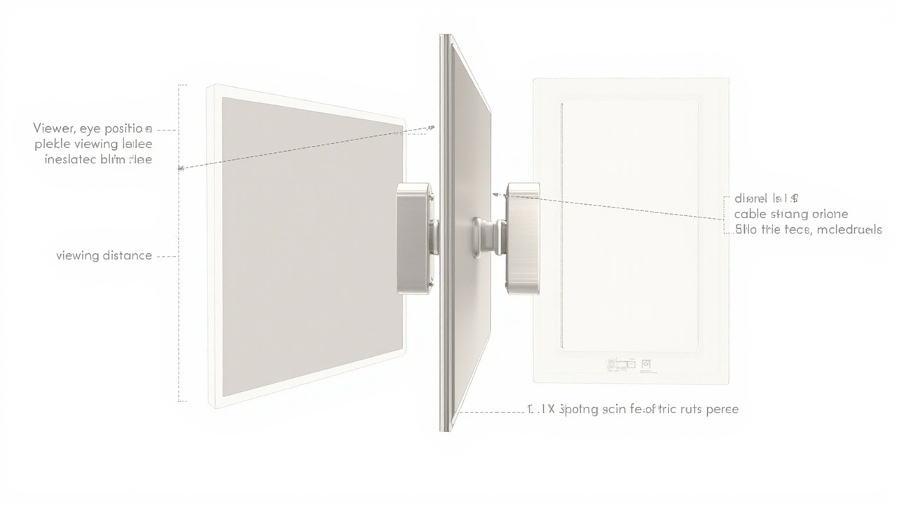
Mounting geometry: viewer eye position, viewing distance, rear clearance, and cable strain relief are the four physical integration variables that most affect day-to-day use.
Pre-install checklist and next steps
Before powering on the 3D display screen for the first time, confirm:
- The selected model’s input list matches the host GPU’s outputs.
- The cable run length is within the cable’s certified range for the chosen timing.
- The host GPU offers the display’s native resolution and refresh in its display settings.
- The source application can emit a stereo format the display accepts (validated via the Content-to-3D Path Checker).
- The display’s mounting position fixes the primary viewer’s eye position at the panel’s recommended viewing distance.
- Rear clearance meets the manufacturer’s ventilation specification.
- A second monitor or sharing arrangement exists for collaborators who are not the primary viewer.
When issues appear after install, work through the chain from the application outward — pipeline, GPU output, cable, display controller, viewer sweet spot — rather than assuming the panel itself is faulty. Most integration failures are upstream of the display.
For readers who reached this page while still deciding which model to integrate, the Spatial 3D Display Buying Guide and the Display Selector cover the model-fit questions. This page will continue to apply once that choice is made.
Ready to explore 3D displays?
Browse our detailed comparisons and buying guides to find the right spatial display for your workflow.
View Best 3D MonitorsDisclosure: This article is part of 3DMonitor.net's educational content. Product recommendations are based on research and may contain affiliate links. See our full disclosure.